In the design and maintenance of hydraulic and pneumatic systems, circuit diagrams act as a universal technical “language.” These diagrams allow engineers, technicians, and operators to understand how a system works, identify problems, and implement efficient solutions.
For anyone involved in hydraulic cylinders, valves, pumps, or automation equipment, mastering these diagrams is not optional—it is an essential skill. With over 20 years of experience in hydraulic cylinder manufacturing, JW Hydraulic has seen how proper understanding of circuit diagrams leads to faster troubleshooting, safer operations, and more efficient system design.
This article provides a comprehensive guide to common component categories, standard symbols, and their core functions in hydraulic and pneumatic circuit diagrams.
Core Classifications of Circuit Components
Circuit diagrams can be broken down into several major categories of components, each with distinct roles in system performance.
| Category | Key Components | Primary Function |
|---|---|---|
| Universal Drawing Elements | Pipelines, crossing lines, control lines, connections | Show flow paths and control signals |
| Power & Energy Storage | Pumps, tanks, motors, filters, accumulators, relief valves | Generate, store, and regulate system power |
| Actuators | Hydraulic cylinders, pneumatic actuators, fluid motors | Convert fluid energy into mechanical motion |
| Control Elements | Flow control valves, check valves, pressure control valves, directional control valves | Regulate flow, pressure, and direction |
| Auxiliary Devices | Switches, gauges, heat exchangers, disconnects, mufflers | Provide monitoring, safety, and convenience |
Key Circuit Components and Symbols
Below are the most common hydraulic and pneumatic components, their functions, and practical notes for interpreting their symbols.
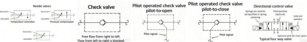
1. Flow & Direction Control
- Needle Valves: Adjust or shut off flow; some include pressure or temperature compensation.
- Check Valves: Permit flow in one direction only.
- Pilot-operated Check Valves: Allow controlled reverse flow when pilot pressure is applied.
- Directional Control Valves (DCVs): Direct flow paths, available in 2/2, 3/2, or 4/3 configurations with multiple neutral positions.
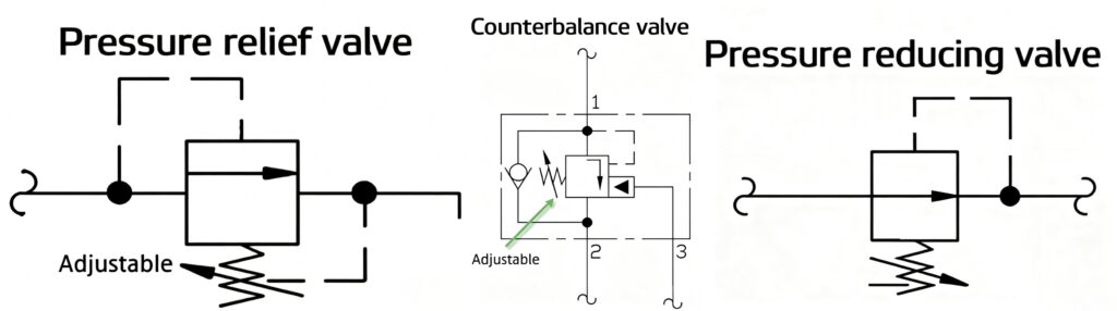
2. Pressure Control
Relief Valves: Protect systems by limiting maximum pressure.
Unloading Valves: Divert flow when not required, reducing energy loss.
Sequence Valves: Ensure operations occur in proper order.
Counterbalance Valves: Control overrunning loads, e.g., gravity in lifting systems.
Pressure Reducing Valves: Maintain reduced pressure in branch circuits.
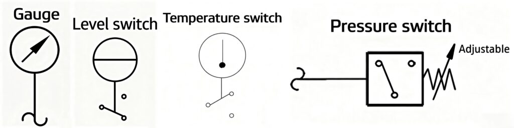
3. Measurement & Monitoring
Pressure Gauges: Display real-time pressure (bar/PSI).
Level Switches: Detect minimum oil levels in tanks.
Temperature Switches: Monitor operating fluid temperature.
Pressure Switches: Trigger alarms or controls when preset thresholds are reached.
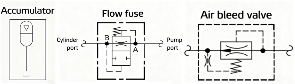
4. Energy Storage & Safety
Accumulators: Store energy, absorb shocks; must always be depressurized before servicing.
Flow Fuses: Close automatically when abnormal pressure differentials occur, protecting actuators.
Air Bleed Valves: Release trapped air, preventing cavitation.
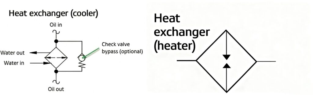
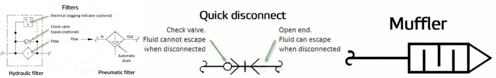
5. Auxiliary Components
Heat Exchangers / Coolers: Remove excess heat (air-to-oil or water-to-oil types).
Heaters: Ensure smooth startup in cold environments.
Filters: Capture contaminants; may include bypass valves and contamination indicators.
Quick Disconnects: Enable fast separation of components (with or without check valves).
Mufflers: Reduce exhaust noise in pneumatic systems.
6. Actuators
Hydraulic Cylinders: Convert fluid energy into linear mechanical motion (single-acting, double-acting, telescopic).
Pneumatic Actuators: Perform linear motion using compressed air.
Fluid Motors: Produce rotary motion, driven by hydraulic flow.
Why Mastering Circuit Diagrams Matters
Understanding hydraulic and pneumatic circuit diagrams is not just about reading symbols—it’s about ensuring:
Faster troubleshooting: Quickly pinpointing faulty components.
Safe operation: Recognizing safety devices like relief valves and accumulators.
Optimized design: Choosing the right components for efficiency and performance.
Reduced downtime: Preventing trial-and-error repairs by diagnosing accurately.
For industries relying on hydraulic cylinders and fluid power systems, this knowledge translates directly into higher productivity and lower maintenance costs.
Conclusion
Hydraulic and pneumatic circuit diagrams are the mechanical language of fluid power systems. By mastering the symbols and understanding the functions of pumps, valves, actuators, and auxiliary devices, technicians and engineers can interpret system operations, design more efficient circuits, and troubleshoot issues with confidence.
At JW Hydraulic, we not only provide high-quality hydraulic cylinders and system components, but also share our technical expertise to help customers worldwide achieve safer, more reliable, and longer-lasting fluid power systems.
👉 Contact us today to learn more about our hydraulic solutions and engineering support.